USB-UART Adapter
A small USB dongle built around a bridge chip (FT232, CP2102, CH340) that turns a target's TX/RX/GND pins into a /dev/ttyUSB port, the standard way to reach a device's serial console.
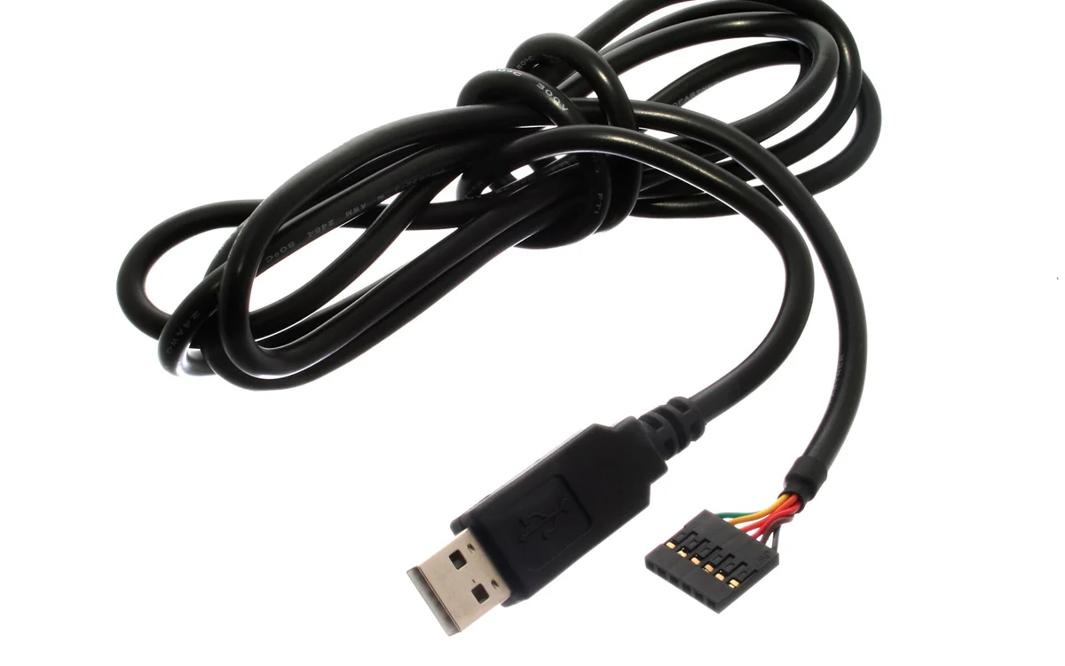
A USB-UART adapter (also called a USB to serial adapter, TTL serial cable, or console cable) is a small dongle whose bridge chip converts USB into an asynchronous serial link at logic level. It is the piece of hardware that connects your laptop to a target's Wiki: uart-header, and for most embedded work it is the single most used tool on the bench.
What it is
The adapter is one chip and a connector. The chip enumerates over USB and presents a serial port to the host, then drives a TX line and reads an RX line at 3.3V or 5V logic level. Common bridges:
| Chip | Linux driver | Notes |
|---|---|---|
| FTDI FT232R / FT232H | ftdi_sio |
see Wiki: ftdi-ft232, FT232H also does JTAG/SPI via MPSSE |
| Silicon Labs CP2102 / CP2104 | cp210x |
very common on cheap boards |
| WCH CH340 / CH341 | ch341 |
cheapest, occasionally flaky clones |
| Prolific PL2303 | pl2303 |
many counterfeits, some refused by vendor drivers |
Under Linux these appear as /dev/ttyUSB0. A device that implements USB CDC-ACM natively instead (an ESP32-S3 or an RP2040 board, for example) appears as /dev/ttyACM0. Either way the port then behaves like any serial port and takes a baud rate, usually 115200 8N1.
Why it matters
This is the cheapest path to a device's own debug output. With three wires you get the bootloader banner, the kernel log, and frequently a login prompt or an unauthenticated root shell. The same adapter also carries flashing traffic: esptool talks to an ESP32 over it, and U-Boot happily accepts commands typed into it. Nothing else gives you that much of a device's internals for that little money.
How to use it
Wire TX to RX, RX to TX, GND to GND. Leave VCC alone unless you are deliberately powering a bare module.
# Which port did it enumerate as?
dmesg | tail -20
ls -l /dev/ttyUSB* /dev/ttyACM*

# Talk to it. 115200 8N1 first, then sweep if the output is garbage.
picocom -b 115200 /dev/ttyUSB0
screen /dev/ttyUSB0 115200

# Same adapter, flashing an ESP32.
esptool.py --port /dev/ttyUSB0 flash_id
If you get Permission denied on the port, add yourself to the dialout group (sudo usermod -aG dialout $USER, then log out and back in) rather than running everything as root.
Logic level, the part that damages boards
The bridge chip's IO voltage must match the target. Most embedded targets are 3.3V.
- A 5V TTL adapter on a 3.3V target can damage the target's RX pin and the SoC behind it.
- The 3.3V/5V jumper on many cheap modules switches only the VCC output pin, not the IO level of TX/RX. Read the module's schematic or measure before trusting it.
- An RS-232 cable is not a TTL adapter. RS-232 swings roughly plus or minus 12V and is inverted; connecting a DB9 serial cable straight to a 3.3V header destroys the pin. TTL means logic level, idle high at VCC.
The safe check is a Wiki: multimetre on the target's idle TX line before you connect anything: idle high tells you the level the board expects.
Pitfalls
- TX/RX swapped. The classic. Total silence, no error message. Swap the two data wires before you doubt anything else.
- Wrong baud rate. Rhythmic garbage rather than silence. Sweep 115200, 57600, 38400, 9600.
- No common ground. Without a shared GND the two sides have no voltage reference and you get noise or nothing.
- Back-powering. VCC connected to a self-powered board fights its regulator and causes resets. Share ground only.
- Counterfeit chips. Clone FT232R and PL2303 parts exist in volume and vendor drivers have historically refused or bricked them on Windows. On Linux the mainline drivers do not care, which is one reason people keep a Linux box for serial work.
- Only three usable pins. Many targets bring out TX/RX/GND and nothing else, and some depopulate RX so the console is read-only by design. That is the vendor hardening, not your wiring.
Further reading
Used in these courses
UART is the most common debug interface left exposed on IoT devices. This course takes you from understanding the electrical signal all the way to getting a root shell - the exact path a hardware hacker follows in the field. Every major embedded device you'll ever audit has UART. Learn it once, use it everywhere.
U-Boot Debug Header Secrets**Beginner** probe lab. Clip onto a U-Boot serial console, find the non-default baud, dump the bootloader environment to leak a provisioning secret, then read the fused OTP key and unlock the secure region. Model B: bring your own probe CLI, flags travel over the line.