Multimeter
Measures voltage, continuity, and resistance. On the hardware bench it is how you map an unknown header and confirm logic levels before you ever connect an adapter.
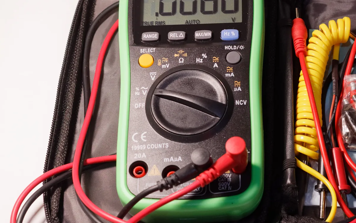
A digital multimeter (DMM) is the most basic and most used instrument on the hardware bench. It measures DC voltage, continuity (is there a connection?), and resistance, and most models add current, capacitance, diode, and frequency ranges. In hardware hacking you rarely need the fancy ranges: you need voltage and continuity, and you need them before you connect anything, because a wrong assumption about a pin is what fries a target or an adapter.
What it is
A handheld unit with a rotary function switch, a two-line display, and two probes: black into COM, red into the VΩ (volts/ohms) jack. The two settings that earn their keep in hardware work are:
- Continuity (the sound-wave icon): the meter beeps when resistance between the probes is near zero. This is how you find which pins are electrically the same net, especially which pad connects to ground.
- DC voltage (
Vwith a straight line): with the board powered, this reads the steady level on a rail or the idle level on a signal line, so you learn whether the device is a 3.3V or a 5V target.
Why it matters
Getting the level wrong is expensive. Wire a 3.3V USB-UART adapter to a 5V line, or swap GND and VCC, and you can damage your gear, the target, or both. A multimeter removes the guesswork: you identify each pin, confirm the rail voltage, and only then match your adapter and connect. It is the cheapest insurance on the bench.
Finding a UART header on a PCB
A four-pin header near the main SoC is very often the UART console. Here is how to label it without a datasheet:
- Continuity mode. Probe each pin against a known ground, a metal shield or a large copper plane, with the board off. The pin that beeps is
GND. - DC voltage mode, board powered. A pin that sits steady at
3.3Vor5Vand never moves isVCC. Note the value: that is your target logic level. Do not useVCCfor signalling. - Read the remaining two pins at idle:
- Near
VCCand steady is likely TX, because an idle UART line rests HIGH. - Near
0Vis likely RX. - A pin that flickers during boot is an active TX carrying data, the console talking.
Confirm the rail so you can set your adapter, then wire target TX to adapter RX and vice versa, grounds common.
Pitfalls
- Continuity needs the board off. Buzzing out a net on a powered board gives false readings and can be unsafe; power down and let capacitors bleed first.
- TX vs RX by voltage alone is a hint, not proof. Both may idle high. The flicker-during-boot test and a logic analyzer capture are what actually confirm which is TX.
- A steady high is not always VCC. An idle TX also sits near the rail. Use continuity and the boot-time flicker to tell a supply rail from a signal.
- Meter your own supply. Before trusting a reading, verify the meter on a known source (a fresh AA reads ~1.5V). A flat meter battery skews everything.