Multimeter
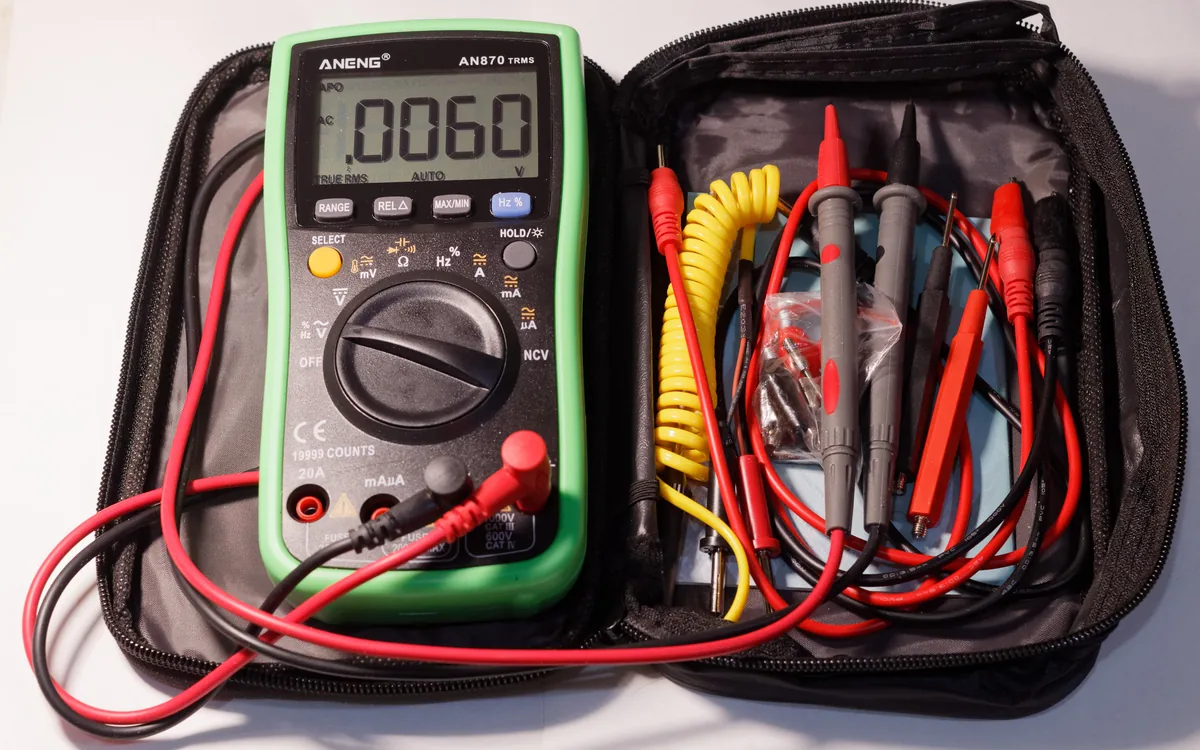
What it does
A multimeter measures voltage, continuity, and resistance. In hardware hacking it is how you map an unknown header and confirm logic levels before you connect an adapter, so you don't wire a 3.3V adapter to a 5V line, or swap GND and VCC into something that doesn't like it.
Use cases
Continuity mode against a known ground plane or shield: the pin that beeps is GND.
DC voltage mode on a steady pin tells you 3.3V or 5V before you pick an adapter jumper setting.
An idle UART TX line sits HIGH near VCC; RX sits closer to 0V until data flows.
How you use it
The standard header-mapping procedure, done before anything gets clipped or soldered:
# 1. continuity mode: probe each pin vs a known GND plane -> the beeping pin is GND
# 2. DC voltage mode, board powered: a steady 3.3V/5V pin is VCC, do not use it for signalling
# 3. read remaining pins at idle: near-VCC and steady = likely TX, near-0V = likely RX
# 4. a pin that flickers during boot is an active TX carrying dataAlways confirm VCC's level. Match your adapter (3.3V or 5V) to what you measured, never assume.
Idle isn't proof. A steady HIGH pin can also be a pull-up; corroborate with a flicker during boot before you call it TX.