FTDI FT232RL
The reference USB-to-UART bridge for reaching a device's TTL serial console. Turns a USB port into /dev/ttyUSB0 so you can read boot logs and drop into a bootloader or root shell.
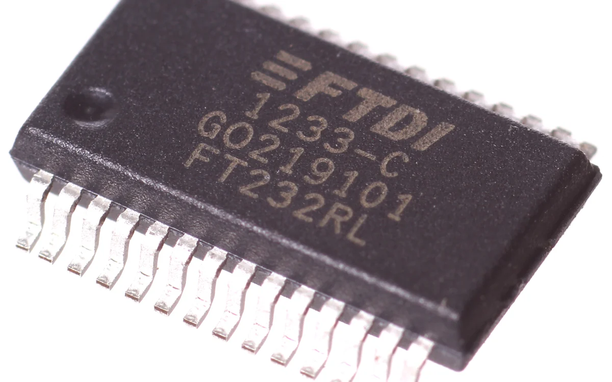
The FTDI FT232RL is a USB-to-UART bridge IC, the reference adapter for connecting a PC to a device's TTL serial console during hardware hacking. The chip pictured is the part that sits on countless "USB to serial" breakout boards and cables; plug one in and it enumerates as a /dev/ttyUSB0 serial port.
What it is
The FT232RL is a single chip from FTDI that converts between USB and an asynchronous serial (UART) line. It handles USB enumeration, exposes standard TX/RX data lines plus the RTS/CTS/DTR/DSR modem-control signals, and has an internal oscillator and EEPROM so a board needs almost nothing else around it. Its VCCIO pin sets the logic level of the serial lines, so the same chip can talk to 3.3V or 5V targets. FTDI's Linux and Windows drivers are mature and ship in-tree, which is why the FT232RL became the default even though cheaper alternatives (CP2102, CH340) do the same job.
Why it matters
Most embedded debug consoles speak plain UART at logic levels, not RS-232 voltages and not USB. Without a bridge, your PC cannot see them at all. An FT232RL turns that console into an ordinary serial port you can open with any terminal. A live UART console is often the single fastest win in hardware hacking: it streams the bootloader banner and kernel log, frequently lets you interrupt U-Boot to change the boot arguments, and on badly configured devices drops you straight to an unauthenticated root shell, no flash desoldering required.
How it works
On the USB side the chip is a full-speed device; on the serial side it is a UART transmitting frames at a configured baud rate. You pick the baud, the driver programs the FT232RL's internal clock divider, and bytes written to /dev/ttyUSB0 go out on TX one start-bit-framed byte at a time. The receiver samples the target's TX line at the same baud and hands you the bytes back. Everything hinges on both ends agreeing on baud rate and framing (almost always 8N1).
How to use it
Wire it crossover (see the diagram), set the level to match the target, then open a terminal:
# List the port after plugging in.
dmesg | tail                       # look for ttyUSB0 / FTDI

# Open the console. 115200 is the common default; try others if it is garbage.
picocom -b 115200 /dev/ttyUSB0
screen /dev/ttyUSB0 115200

# Unsure of the baud rate? Sweep the usual suspects.
for b in 115200 57600 38400 9600; do echo "== $b =="; timeout 3 picocom -qrb $b /dev/ttyUSB0; done
Readable text at a given baud confirms you have the wiring and speed right. Garbage that changes with baud means the rate is wrong; garbage that never resolves usually means TX and RX are swapped, or the level is wrong.
Pitfalls
- Logic level. Most modern boards are 3.3V. Set the adapter jumper to 3V3 (drive
VCCIOfrom 3.3V) and never push 5V into a 3.3V RX pin. - Do not back-power. If the target is self-powered, leave the adapter VCC disconnected and share only GND. Feeding VCC into a live board can fight its regulator or damage it.
- Crossover, not straight. TX goes to RX and RX goes to TX. Wiring TX to TX is the classic beginner mistake and produces silence.
- Counterfeits. FTDI drivers have historically bricked or garbled counterfeit FT232RL chips. If a "genuine" board misbehaves under FTDI's driver, a clone chip is a likely cause.