CH341A
Cheap USB programmer that reads and writes 25-series SPI flash and 24-series I2C EEPROM chips. Paired with a SOIC-8 clip and flashrom, it dumps a device's firmware for a few euros.
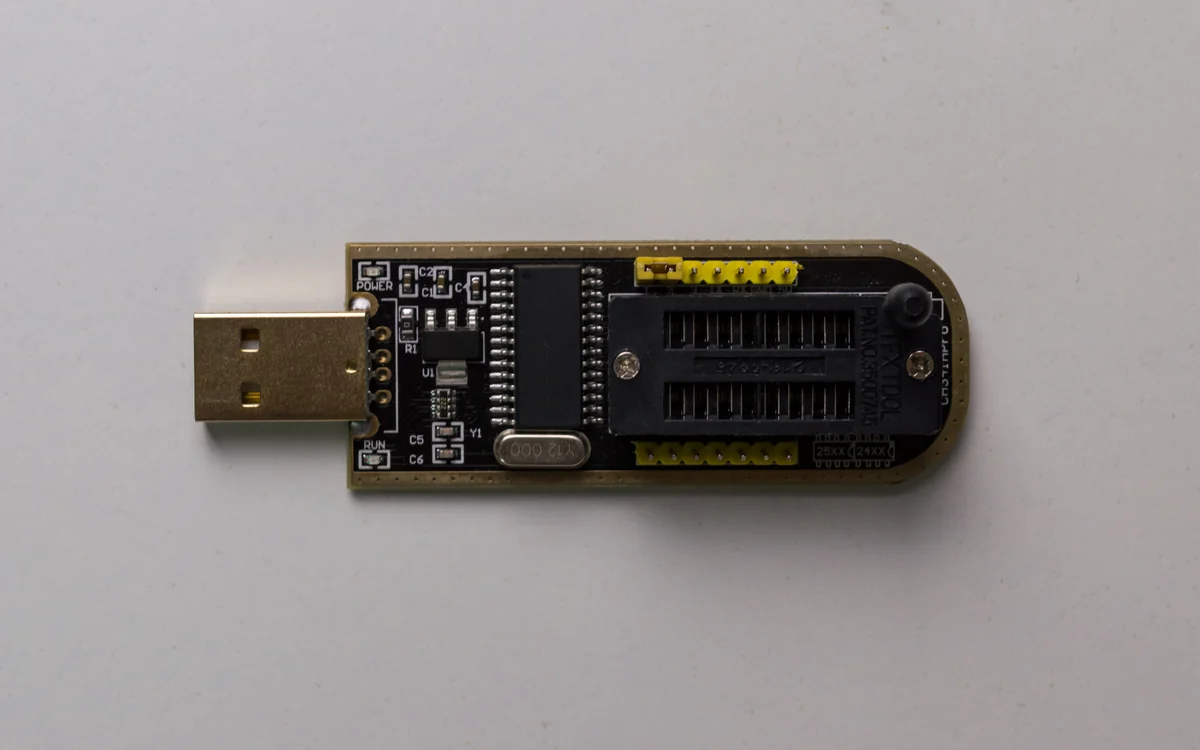
The CH341A is an inexpensive USB programmer, built around the WCH CH341 USB bridge chip, that reads and writes 25-series SPI flash and 24-series I2C EEPROM chips. The common black "CH341A mini programmer" board pictured is the go-to budget tool for dumping firmware off a SOIC-8 flash for a few euros, with no shell, network, or credentials required.
What it is
The CH341 is a multi-protocol USB bridge: in one mode it is a USB-serial converter, in another it drives SPI, I2C, and parallel buses. The cheap programmer boards wire the chip's SPI and I2C lines to a DIP-8/SOIC-8 socket and a small pin header. That single board covers the two memory families you meet most on the bench: 25-series SPI NOR flash (firmware) and 24-series I2C EEPROM (config). Under Linux it needs no vendor driver; flashrom talks to it directly through libusb as the ch341a_spi programmer.
Why it matters
Firmware usually lives in an external SPI flash chip soldered next to the SoC. If you can read that chip, you have the entire image offline: bootloader, kernel, root filesystem, and any secrets baked into it, with no need to log in. The CH341A is the cheapest reliable way to do that. Combined with a SOIC-8 clip it reads the flash in-circuit, without desoldering, which makes it the fastest non-destructive route to a device's firmware.
How it works
flashrom probes the flash JEDEC ID over SPI, looks it up in its chip database to learn the size and the erase/write opcodes, then streams the whole address space out over USB. Reading is passive: it only issues READ commands, so a clean read leaves the chip untouched. Writing erases sectors and programs them back, which is how you patch and reflash. The board itself is dumb; all the intelligence about a given chip lives in flashrom.
How to use it
Put the flash chip (or the clip) in the socket, pin 1 to pin 1, then:
# Identify the chip. flashrom prints the detected part and its size.
flashrom -p ch341a_spi

# Read the flash twice and compare - a good dump is reproducible.
flashrom -p ch341a_spi -r r1.bin
flashrom -p ch341a_spi -r r2.bin
sha256sum r1.bin r2.bin        # the two reads must match

# If detection is flaky, slow the SPI clock down.
flashrom -p ch341a_spi:spispeed=128k -r dump.bin

# Force a chip type when the ID is ambiguous.
flashrom -p ch341a_spi -c "W25Q64.V" -r dump.bin
With dump.bin in hand, run binwalk to carve the partitions and extract the rootfs, then reverse the firmware offline.
Pitfalls
- Voltage. Many black CH341A boards drive the SPI lines and the socket VCC at 5V, which can stress or damage a 3.3V flash chip. Prefer a 3.3V-modified board, or add a level shifter, before touching a modern part. This is the single most common way people kill a target chip.
- In-circuit contention. Reading in-circuit with a clip means the board's own CPU may fight you for the bus. Power the board down, or hold the SoC in reset, so only the programmer drives the flash.
- Two reads, always. A single read can look fine and still be corrupt from a poor clip contact. Read twice and diff; if the hashes differ, reseat and lower the clock.
- Not a debugger. The CH341A reads memory chips, not CPUs. For halt/step access to a processor you need JTAG or SWD, not this.
Further reading
Used in these courses
You have a firmware blob. What now? This course teaches the complete analysis workflow: identify the format, extract the filesystem, explore the structure, and find what matters. Every IoT device has firmware - this is how you read it.
Wired Chip Access: SPI Flash and JTAG**Beginner** probe lab. Wired-bus tradecraft with the probe CLI against two intro boxes: a block-protected SPI NOR flash and a JTAG-locked microcontroller. Model B: bring your own probe CLI, flags travel over the wire.