Logic Analyzer
Samples several digital lines at once and, with sigrok/PulseView, decodes them back into UART, SPI, and I2C bytes. Turns unlabelled test points into a readable transcript of the bus.
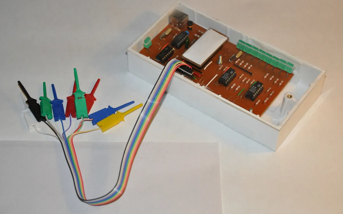
A logic analyzer records the logic level (high or low) of several digital lines at the same time and at a known sample rate, then hands the capture to software that decodes it into protocol bytes: UART, SPI, I2C, JTAG, 1-Wire, and dozens more. Where an oscilloscope shows you the analog shape of one signal, a logic analyzer shows you the meaning of many signals at once.
What it is
The tool most people start with is the cheap 8-channel USB clone: a small board built around a Cypress FX2 chip that presents eight input channels and streams samples to the host over USB at up to 24 MHz. It is driven by the open-source sigrok library and its GUI PulseView, and it happily impersonates the Saleae Logic protocol. Serious work uses a genuine Saleae or a bench instrument, but for hardware recon the clone is enough to read most low-speed embedded buses. The board ships with flying leads and grabber clips that hook onto pins and test points.
Why it matters
Open an IoT device and you will find rows of unlabelled pads and test points. A logic analyzer is how you turn that into knowledge: which pad is a clock, which carries data, what speed the bus runs at, and what it is actually saying. It changes the game from guessing at a pinout to reading a decoded transcript of real traffic, which is often where credentials, debug menus, and firmware-update chatter leak out.
How you use it
Install the stack and launch the GUI:
sudo apt install sigrok-cli pulseview
pulseview            # or drive it headless with sigrok-cli
Clip the analyzer's ground to the board ground first, then connect channels to the pins of interest, and capture while the device boots or does something interesting. In PulseView you add a protocol decoder (Menu -> Add decoder), point it at the right channels, and the raw waveform becomes bytes.
Finding an unknown UART baud rate
Boot is the chatty moment, so capture then:
- Trigger a capture and reset the target so the console prints.
- Zoom in and measure the shortest single pulse, that is one bit time. Say it reads
8.68 us. - Baud is
1 / bit_time:1 / 8.68usis about115200. - Set that baud in PulseView's UART decoder and the console text appears; feed it to your
usb-uartadapter to interact live.
The same measure-the-shortest-pulse trick recovers an SPI or I2C clock rate before you add those decoders.
Pitfalls
- Share a ground. Without a common ground reference the capture is noise. The ground clip is not optional.
- Sample fast enough. Sample at least 4x (ideally 8-10x) the bus speed, or edges land in the wrong place and decoding fails. The 24 MHz clone cannot cleanly read a 50 MHz SPI flash.
- Levels and protection. A bare FX2 clone has little input protection and is happiest at 3.3V logic; check the target rail with a multimeter and do not feed it anything higher than it tolerates.
- Decode is a guess until confirmed. A decoder will emit plausible-looking bytes even on the wrong channel or baud. Sanity-check against known strings (a boot banner, an ASCII prompt) before you trust it.
Further reading
Used in these courses
**Beginner** probe lab. Clip onto a U-Boot serial console, find the non-default baud, dump the bootloader environment to leak a provisioning secret, then read the fused OTP key and unlock the secure region. Model B: bring your own probe CLI, flags travel over the line.
Firmware IoT: Extraction & AnalysisYou have a firmware blob. What now? This course teaches the complete analysis workflow: identify the format, extract the filesystem, explore the structure, and find what matters. Every IoT device has firmware - this is how you read it.