Logic analyzer
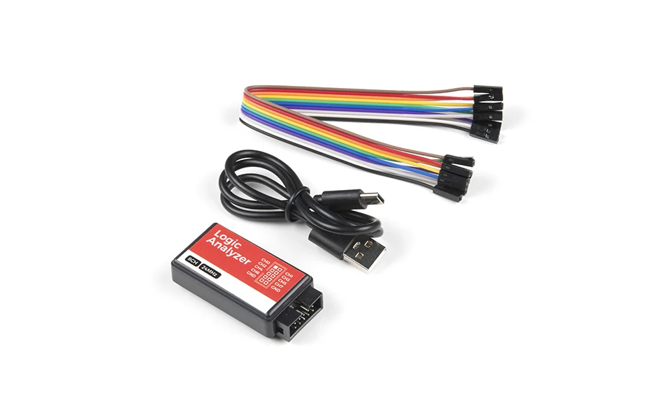
What it does
A logic analyzer captures multiple digital signals over time and, with software like sigrok/PulseView, decodes them into protocol bytes for UART, SPI, I2C, JTAG and more. When you find unlabelled test points on a board, it tells you what they are: which pin is a clock, which carries data, and at what speed.
Use cases
Capture all the candidate pins at once and let the UART/SPI/I2C decoders tell you which one is which.
Zoom in on the shortest pulse during boot, measure it, and derive the baud rate from the bit time.
Tap SPI or I2C lines while the board runs normally and read the traffic without interrupting it.
How you use it
Install the open-source stack, then connect ground and the channels of interest and capture while the device boots or operates:
sudo apt install sigrok pulseview
sigrok-cli -d fx2lafw --scan
sigrok-cli -d fx2lafw --samples 1M -c samplerate=4MHz -o cap.sr
# open cap.sr in PulseView, stack a UART/SPI/I2C decoder
Wiring
Sample fast enough. Sample at least 4x the signal's fastest edge or you get aliasing artefacts instead of a clean decode.
Share a ground. Always tie the analyzer's ground to the board's ground, or the captured levels drift and decoders miss framing.