SPI Flash (SOIC-8)
The small 8-pin chip that stores a device's firmware. Clip it or desolder it, dump the whole image over SPI, and you have the firmware offline with no network and no login.
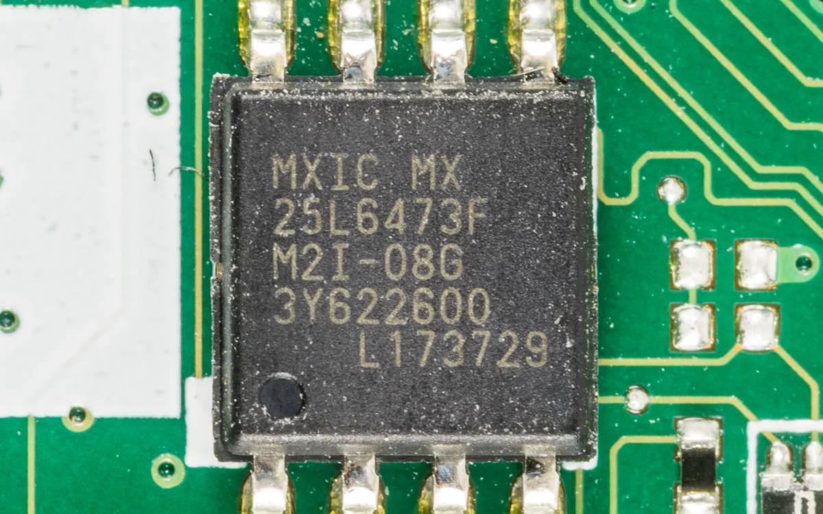
SPI flash is the small 8-pin chip (SOIC-8, or the leadless WSON-8) that holds a device's firmware, read and written over the SPI bus. It is the 25-series NOR flash you see soldered next to the SoC on almost every consumer board; the Macronix MX25L part pictured is a typical example.
What it is
NOR flash stores the code and data a device runs. On systems with an external SoC (routers, cameras, many IoT boards) the whole firmware image lives here: the bootloader, the kernel, the root filesystem, and the configuration. The chips share a near-universal command set and a standard pinout, so one clip and one tool read almost any of them. Common families are Winbond W25Q, Macronix MX25L, GigaDevice GD25, and ISSI IS25; the 25 prefix and a size code (for example W25Q64 = 64 Mbit = 8 MB) tell you the vendor and capacity. Do not confuse them with 24-series I2C EEPROMs, which use a completely different bus.
Why it matters
Dump the flash and you hold the entire firmware image offline: no network path, no authentication, no running services to fight. It is the canonical first move when a UART console gives nothing, and it is where hardcoded secrets, private keys, and backdoors are found. Because the chip is external and standard, reading it is cheap and repeatable.
How it works
SPI is a four-wire synchronous bus: /CS selects the chip, CLK clocks the bits, DI/MOSI carries commands and write data into the chip, and DO/MISO carries read data out. To read, the host asserts /CS, sends a READ opcode and a start address, then clocks out bytes until it releases /CS. flashrom first sends the JEDEC 9F identify command to learn the manufacturer and capacity, then streams the whole address space out. Quad-SPI parts repurpose /WP and /HOLD as two extra data lines (IO2/IO3) for speed, but plain single-SPI reads work for dumping.
How to attack it
- Read the markings. Note the part number (for example
MX25L6473F) and decode the size. - Get at the pins. Clip it in-circuit with a SOIC-8 test clip, or desolder it with hot air onto an adapter.
- Dump it, twice. A good dump is reproducible.
flashrom -p ch341a_spi                 # identify: prints part + size
flashrom -p ch341a_spi -r dump1.bin
flashrom -p ch341a_spi -r dump2.bin
sha256sum dump1.bin dump2.bin          # must match

binwalk dump1.bin                      # find partitions
binwalk -e dump1.bin                   # carve and extract the rootfs
strings dump1.bin | grep -i -E 'passwd|key|token'
With the image extracted, mount or carve the filesystem, hunt for credentials, and reverse the interesting binaries.
Pitfalls
- Voltage. These are 3.3V parts. A 5V programmer or clip supply can damage the chip; use a 3.3V board or a level shifter.
- Bus contention in-circuit. The board's CPU may also drive the flash. Hold it in reset or cut its power so only the programmer talks to the chip.
- Encrypted flash. On platforms with Flash Encryption enabled (for example a hardened ESP32) a raw dump is only ciphertext. Check the security posture before assuming the image is readable.
- Package. A leadless WSON-8 has no legs for a clip; it needs a socket adapter or desoldering.
Further reading
Used in these courses
You have a firmware blob. What now? This course teaches the complete analysis workflow: identify the format, extract the filesystem, explore the structure, and find what matters. Every IoT device has firmware - this is how you read it.
Wired Chip Access: SPI Flash and JTAG**Beginner** probe lab. Wired-bus tradecraft with the probe CLI against two intro boxes: a block-protected SPI NOR flash and a JTAG-locked microcontroller. Model B: bring your own probe CLI, flags travel over the wire.